|
|
 |
Read lesson 9b. Then complete hw 9b. Frame Relay X.25 had many advantages over older protocols, but there are some disadvantages to using X.25 as well.
X.25 is extremely reliable and this reliability is needed when networks have high error rates.
X.25 establishes a virtual circuit through the network. Frame Relay does this, too. A connection oriented service uses a call setup procedure to establish this virtual circuit. So, we can say the main difference between X.25 and Frame Relay as follows:
Current digital networks operate with very low error rates. All the overhead in an X.25 network is unnecessary. High quality equipment and high quality lines make the overhead a waste of capacity. Do we really need to give away capacity to make sure we catch one error per day? Wouldn't it be better just to let a higher layer take care of the error and request a retransmission, and then reclaim, for example, 10% of our capacity? Of course it would. Frame Relay was developed to take advantage of very low error networks. Here are some highlights of Frame Relay:
Wow, we just cut out a whole bunch of overhead. A Frame Relay frame header should be pretty small. But wait a minute. Won't there be some problems if we don't have any flow control or error control?
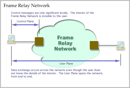
Potential problems in a Frame Relay Network Frame Relay communications can be divided into two realms. The user plane and the control plane. Communications from end to end for information transfer by the user define the user plane. Communications between the end user and the Frame Relay network for controlling the network define the control plane.
Frame Relay Control Plane
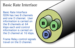
Running Frame Relay over a BRI ISDN link permits all the control information to be passed on the D channel. No control information takes up capacity on the informational channels, the B channels. In this case, the user could get the full 128,000 bits per second for information transfer. Control messages follow a particular protocol for exchange on the D channel called LAP-D. LAP-D is an HDLC derivative. LAP-D highlights follow:
On a T1 line using DS1 framing, 23 channels (B channels) are used for user information transfer and the remaining channel (D channel) is used as a control channel. In this case, the D channel supports 64 kbps as do the B channels. The D channel will exchange messages using LAP-D. Frame Relay User Plane
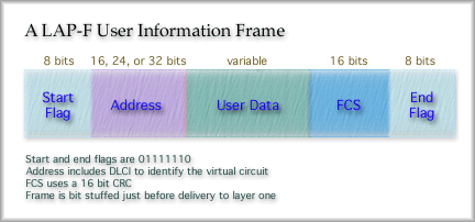
Because there is no error or flow control, the header for this HDLC variant is small. Take a look at the Frame Relay frame.
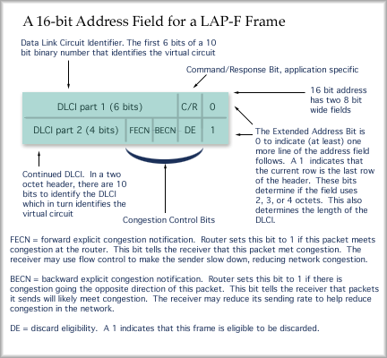
Compare this with an HDLC frame. Here, there is no control field. The control field was where we had sequence numbers that provided flow control. The control field also allowed us to send error control messages as well. While LAP-F checks for errors with a 16-bit CRC, it will not notify the sender if the frame has an error. Erred frames are discarded. The address field is used to identify the virtual circuit. It contains the DLCI and a few other fields. Take a look at how the address field is broken down for a 2 octet address field, which is the default size.
The address field serves many purposes. The DLCI identifies the virtual circuit. Once the packet gets to the Frame Relay network, a frame handler will direct it through the frame relay network using the DLCI. In a two octet header there are 10 DLCI bits. That means: 210 unique values which means 1024 virtual circuits For a three octet header (Figure 10.7, pg. 313) there are 17 bits for the DLCI. For a four octet header there are 24 bits for the DLCI. These numbers would give us: 217 unique values or 131,072 virtual circuits A DLCI number is determined for use only between the end station and the frame handler at the edge of the Frame Relay network. The DLCI value is probably different on the other side of the network. The Frame Relay network holds responsibility to deliver the packets to the other end in order, but how it does this is not supposed to concern the end user. A variety of protocols might be used to move the frames from the entry to the Frame Relay cloud to the exit from the cloud. Congestion Management in Frame Relay Networks The network can work together with the end stations during operation to control congestion. Frame Relay nodes cannot implement direct flow control. However, three bits are provided in each Frame Relay frame to implement notification and frame discard. The DE bit is used to mark frames for discard, the FECN bit is used to mark frames that have encountered congestion, and the BECN bit is used to mark frames that pass through routers with congestion in the "backward" direction. Congestion may be controlled through cooperation:
Another method of control that the Frame Relay provider has is to control the amount of data coming into his network through contractual agreements with the end users. Frame Relay providers will contract with the end user to provide a Committed Information Rate, or CIR. In theory, as long as you transmit at or below the CIR, your data travels through the network with a high probability of arriving at the destination. The CIR is sometimes called the committed burst size, or Bc. You may exceed the CIR for brief periods of time, but the frame handler will mark your frames as eligible for discard by setting the DE bit to 1. If this frame encounters congestion it will be thrown away, leaving room for frames sent below the users CIR. If you continue to exceed the CIR, you will pass the maximum transmission rate, or Be for excess burst size, for a given period of time. All frames sent after this are discarded immediately. You will not be able to send frames again until the (very short) time period expires. Take care to review a Frame Relay contract carefully. The How is congestion handled when it occurs?
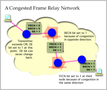
FECN bit set to 1: receiver should use flow control (higher level) to force sender to slow down. i.e. withhold ACK messages that open the window or send an receiver not ready (RNR) message to stop the transmitter. BECN bit set to 1: receiver should reduce its own transmission rate The following graphic shows how a frame, with all three congestion notification bits set to zero at the start, is changed to notify the receiver of network congestion.
Review of congestion control bits: DE bit: The frame handler at the edge of the network keeps track of your incoming data rate. Frames that exceed the CIR are marked as discard eligible by setting the DE bit to one. If a congested intermediate node gets this frame it may, optionally, discard the frame. No notification is sent to the sender or receiver when a frame is discarded. FECN bit: Intermediate nodes set this bit to one if there is congestion moving in the same direction as the frame. With this bit set, this frame tells the receiver, "your higher level protocol should implement flow control to slow down the incoming frames." BECN bit: Intermediate nodes set this bit to one if there is congestion in the opposite direction of the packet. With this bit set, this frame tells the receiver, "frames you send are contributing to congestion, so slow down."
|
| [INF 680 Syllabus] [How to Start] [Schedule] |
Used with permission of the Author; Copyright (C) Kevin A. Shaffer 1998 - 2022, all rights reserved. |
