|
|
 |
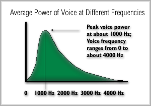
Read pages 236 to 254 and this lesson. Then, complete the hw8 before the lecture. Bring your homework notes to class. Multiplexing Let's begin by defining some simple terms. Multiplexing: combining several communications channels together so they may be transmitted as a single signal on a medium. Demultiplexing: separating multiplexed signals. Why would you want to do this? One reason is to save money. For example, the telephone company combines several telephone conversations into a single signal that it transmits over a single cable. Way back in an earlier chapter you studied how to draw a signal in the frequency domain. We need to return to the frequency domain and take a look at a typical voice signal. The human voice ranges from about 100 Hz to about 4000 Hz. Voice has many different frequency components. The most powerful components are centered around 1000 Hz. The frequency components of voice at higher frequencies are much less powerful. Below 1000 Hz, the power drops off rapidly, too. Take a look at the rough sketch of the average voice power at different frequencies in the graph below.
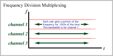
We also noted in an earlier chapter that a typical cable supports a much greater range of frequencies than is required for one voice signal. If there were some way to use those frequencies we could make more efficient use of the bandwidth. Frequency Division Multiplexing
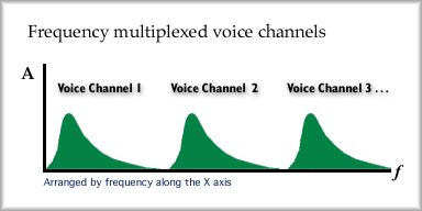
Note that the frequency axis is vertical in the above graphic. Voice signals can be lined up in a row for transmission. Up to about 13,000 channels have been combined onto a single coaxial cable for simultaneous transmission. A few voice signals combined in this way might look like the following diagram.
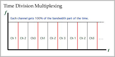
Time Division Multiplexing
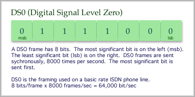
Note that the frequency axis is vertical in the above graphic. Space Division Multiplexing Summary FDM: user gets part of the frequency all the time The T-System The DS0 frame was created to hold one voice sample which is eight bits. A standard digital telephone line will transmit DS0 frames synchronously (one after another with no pauses) to support one telephone conversation.
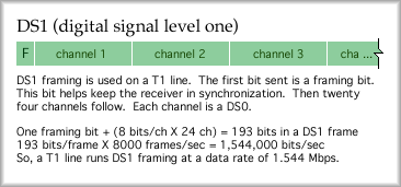
For a quality voice signal, 8000 DS0 frames must be sent per second. This means that to have a quality voice signal, 8000 samples of the voice must be made in one second. Memorize the magic number: 8000 If you order a digital phone line from your local carrier (the phone company), you'll be offered ISDN service at the basic rate. BRI, or basic rate interface, is the standard ISDN offering for the residential market. It is actually two phone lines and a control channel. The lines are called B channels and the control channel is the D channel. Digitized voice samples are sent over the B channel 8000 times per second. Because there are 8 bits per DS0 frame, the data rate on the B channel is exactly 64,000 bits per second. Once your voice samples travel all the way to the carrier's central office, they are multiplexed with other voice samples that are heading off in a similar direction. A T1 line is a physical standard that supports sending DS1 frames. DS1 frames represent Time Division Multiplexed voice samples. Your voice samples must be sent at the (magic number) rate of 8000 per second. Mixed with other voice channels, a very high capacity link is required to support the combination. A DS1 frame is a collection of 24 DS0 frames with one additional bit at the front, called a framing bit. The framing bit is used to keep track of the beginning of the frames as they come in. The framing bit alternates for each DS1 frame.
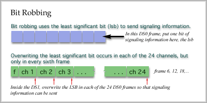
One voice sample from each of the 24 voice channels is placed in the DS1 frame. The whole frame is then sent out and the next frame is constructed. This must happen without delay. If a particular voice channel has no activity, zeros are placed in the channel and it is sent anyway. There are 24 channels in a DS1 and each channel is an 8-bit voice sample. That means there are 192 bits for the channels. There is also a single framing bit at the beginning of the frame. Total everything up and you get 193 bits for a DS1 frame. The DS1 frame contains only one sample from each channel. The samples of a channel have to be sent 8000 times per second. Therefore, 8000 DS1 frames have to be sent in one second. 8000 DS1 frames/sec X 193 bits/frame = 1,544,000 bits/sec = 1.544 Mbps A T1 may also be used to send data. Sometimes the data is simply placed in the voice channels and multiplexed with the voice. This can be a problem because some systems actually steal a bit from the voice channel so that control signals can be sent. Control signals are used to set up, monitor and tear down voice connections. At other times signals are sent on a separate channel to control the connection. In this case, data transmissions are not affected. Bit robbing is a term used to describe using the least significant bit in a single voice channel for signaling. The voice sample bit with the least importance (least significant bit, on the right hand side in our DS0 diagram) is overwritten with the control information. Half the time the bit is, by chance, correct. Of course, the other half the time, the bit is incorrect. For a voice conversation, you'll never notice any difference. However, for a data connection, having a bit in error is fatal. How does bit robbing work and what can we do to send data over a T1 system that uses bit robbing? To send control information along with the voice samples, the least significant bit in every channel of a DS1 frame is overwritten with a signaling bit. This happens once in six frames. The control information is used on a voice link to open the connection, send the dialed numbers from switch to switch, monitor the links state, and disconnect at the end of the call. For data, the control channel might not be used.
To avoid problems when sending data on this link, data is never put in the least significant bit. That means that only 7 bits of a channel are used for data. The eighth bit is reserved for signaling information. So, why not put data into all eight bits for five frames and then use just seven bits for the frame that has bit robbing applied? It turns out that the logic is too expensive to implement. It is cheaper to just set the connection to use 7 bits out of 8 in the channel. Example: What is the data rate on a DS1 in a single channel when the line uses bit robbing? Only seven bits are available for use in sending data. 7 bits/channel X 1 channel/frame X 8000 frames/sec = 56,000 bps Another example: What is the throughput on a T1 line if all channels are used for data and bit robbing is used. Only seven bits are used for data in each channel, but all 24 channels are used. 7 bits/ch x 24 ch/frame = 168 bits are used for data 168 bits of info / 193 bits total = 0.87 --> 87% throughput How is the framing bit used? For DS1 framing, the framing bit alternates between 1 and 0 on each frame. The receiver scans the incoming data until is locates a very long string of these alternating bits. By storing the frames in memory and searching for the pattern, 0101010..., the frames can be "aligned". That is the beginning of each frame can be determined. Example: What is the overhead of a DS1 frame? overhead = overhead bits / total bits = 1 / 193 = 0.00518 What is the overhead data rate? overhead rate = overhead bits in a frame * number of frames per second There were some problems with this type of framing. The frame alignment was easy to lose. Then the link would need to be re-syncrhonized (i.e. search for that 1010... pattern and find the beginning of the frames). Doing this wastes time and forces retransmission of lost data, further slowing the connection. An improved version of framing came about. The standard DS1 frame was used (one frame bit and 24 channels that are 8 bits each), but a group of 12 frames were bundled together and the framing bits were defined in a specific patter for the 12 frames. This permitted more accurate tracking of the beginning of the frames and reduced the number of times that the link had to be re-syncrhonized. The package of 12 frames was called a super frame. Yet, this was still not enough to keep the link up and running for long periods of time without losing track of the beginning of the frames. Extended Super Frame (ESF) was developed to cure this problem. ESF bundled 24 frames together. The frames were still DS1 frames, each with a single framing bit. However, the framing bit was used for several different functions. DS1 framing and Super Frame had a problem in that no statistics were kept by the equipment to show how the health of the link. ESF was developed to help solve this. The framing bits are used in this fashion
The main benefits of ESF include:
|
| [INF 680 Syllabus] [How to Start] [Schedule] |
Used with permission of the Author; Copyright (C) Kevin A. Shaffer 1998 - 2022, all rights reserved. |
