|
|
 |
Read Chapter 7 in your text as well as this lesson. Then complete hw 7. The Data Link Layer Chapter 7 discusses the data link, layer two of the OSI model. Layer one, which you have been studying specified the physical characteristics of a single link, such as converting bits into signals. Layer two is responsible for the logical organization and management of communications sent over that link, such as the location, arrangement and meaning of bits in a frame. For example, the Ethernet card in your computer must arrange bits into frames of a certain size and construct necessary header and trailer information for the frame. There are many tasks that layer two must manage:
These activities can be summarized into three major functions: link management, flow control and error control. Link management includes setting up a connection, monitoring and controlling its activity and tearing down a connection when finished. Flow control is a way to describe techniques that prevent the transmitter from sending frames faster than the receiver can handle them. The receiver has limited buffer space which could fill up, leaving no place to store an incoming frame. Error control describes procedures used to handle frames that have errors, including how to check a frame for errors, what to do when errors are discovered. Please note that error control, error detection and error correction are slightly different concepts. Error Detection -- finding erred frames Error Correction -- finding and correcting erred frames Error Control -- methodology of dealing with erred frames From this point, in lesson six, we'll dig deeper into two types of flow control and three types of error control. Flow Control Consider a conversation with your friend. One of you listens while the other speaks. You might nod your head as you listen or you might interject with a "Whoa, slow down, you're talking too fast!" This is actually flow control. Some of us are better at it than others, but we all do it to some degree. You nod to indicate you understood and are ready for the next morsel of information or you tell your friend when they are going to fast. That's flow control.
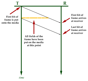
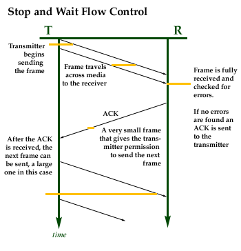
Stop and Wait Flow Control Once the transmitter gets the acknowledgment it can send the next frame. In other words, frames are sent one at a time and each must be confirmed before the next one can be sent. Take a look at the following diagram. The transmitter is on the left (T) and the receiver (R) is on the right. They are separated by some distance. The vertical scale represents time, with time zero at the top. A frame is transmitted and it takes some time to travel to the receiver. The black arrows crossing the diagram show the leading edge and trailing edge of the frame as it travels to the receiver.
Take a look at Stop and Wait Flow Control in the next diagram. Notice that much of the time, the receiver and the transmitter are doing nothing but waiting.
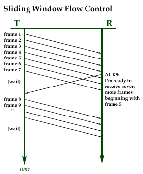
Frames are usually numbered to keep track of them. Acknowledgments are also numbered. Stop and Wait Flow Control need only number the frames as frame 0 and frame 1. The acknowledgments are numbered ACK0 and ACK1. Look how much time the transmitter is doing nothing in the above diagram. When a frame is small, much of the time is spent waiting for it to travel across the network and for the ACK to return. One solution to this problem of poor efficiency is to send larger frames. When frames are larger, more time is spent sending data. Larger frames are more efficient as long as there are few errors. If there is an error the entire frame has to be resent. The larger the frame the more likely there will be an error in it, so there is a point where no benefits are found by increasing the frame size. When there are frequent errors very small frames might be appropriate. Another solution to the poor efficiency is another form of flow control called Sliding Window Flow Control. Sliding Window Flow Control Let's say that the transmitter and the receiver agree that seven frames can be sent at a time. The transmitter starts out with permission to send seven frames. We'll define the number of frames that can be sent as the "window". Frames 1 through 7 may be sent immediately.
If all seven frames are sent, the transmitter has to stop and wait. The receiver may send an ACK when it is ready to receive another 7 frames. The ACK will set the transmitters window back to seven sendable frames. In the case above the receiver has sent an ACK5. This message means that frames 1 through 4 were received correctly and that the receiver is "expecting frame 5 next." When the transmitter gets ACK5 is knows that beginning with frame 5 is may send seven frames. Some of those frames may have already been sent, though, so the transmitter sends the remaining frames in the window. The transmitter has to keep track of which frames in the window have been sent and which can be sent. It has to know which frames have been acknowledged as well. After sending 7 frames in the above diagram, the transmitter has to stop and wait. Once ACK5 arrives it marks frames 1 to 4 as acknowledged and "slides" its seven-frame window down to include frames 5 to 11. Having already sent frames 5, 6, and 7, the transmitter now sends 8 through 11. Then the transmitter waits again. The receiver may choose not to acknowledge frames so that the transmitter will exhaust its supply of sendable frames and stop transmitting. This is how the receiver controls the pace of incoming frames. When the receiver is ready to receive another 7 frames, it can send an ACK. If there are no problems with the incoming pace, the receiver sends frequent ACKs so that the transmitter never exhausts its window. This is where the efficiency is accomplished. The transmitter can send continuously when the receiver processes frames more quickly than they arrive because the receivers buffer space never fills up. Computers work in binary. So, to keep count of frames they will use several bits in the control field of the frame for the send number. They will also have a few bits for the receive number. Since both sides will have information to send, full duplex transmission, both sides will have a window, send numbers and receiver numbers. If three bits are reserved for the send number, then ... L = 2n ... the window size is 8. For most systems, when the last frame is sent, the number rolls over and starts from zero again. Remember that counting in binary starts will zero, not one. Not all sequence numbers roll over to zero upon reaching the window size number. The window size can be smaller, even much smaller than the frame sequence numbers. This roll over could cause a problem. What if the transmitter receives an ACK3, then sends frames 3, 4, 5, 6, 7, 0, 1, and 2, and then receives an ACK3? Is this a repeat ACK3 or a new ACK 3. For this reason the transmitter will always set its window to one less than the maximum. That way the problem cannot occur. This means that:
In practice the most common window sizes at layer 2, the data link layer, are 7 and 127. However, on low-error links of great distance it is beneficial to increase the window size. In summary:
Error Control Three types of error control are discussed in your text. All are collectively called automatic repeat request, or ARQ. The three types of error control are:
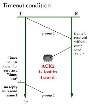
Please don't confuse Stop and Wait Flow Control with Stop and Wait ARQ. These are different concepts that are part of a stop and wait transmission protocol. Stop and Wait ARQ What happens if a frame, an ACK or a NAK are lost in transit? This could be a problem, so when a frame is sent, the transmitter starts a timer. If the timer counts down to zero before an ACK or NAK is received the transmitter resends the frame.
This condition is known as a "time out". Note the following:
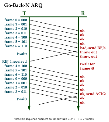
Go-Back-N ARQ This feature guarantees that frames are received in order, but it also means that some good frames may have to be resent.
In the above graphic, note how the transmitter begins by resending the frame that was in error and then continues by sending succeeding frames until its window is exhausted.. Selective Reject ARQ The receiver, upon finding and erred frame, will request that frame be resent and only that frame is resent. The receiver has to keep track of what frames are coming in and what sequence they belong in. Reordering the frames may be required. The receiver cannot deliver frame contents to layer three until the frames have been put in order and no frames are missing in the sequence. The transmitter also has to keep careful track of which frames have been sent, which have been acknowledged and which are available to be sent. Selective Reject ARQ works in combination with sliding window flow control. Selective Reject ARQ is not common at the data link layer. It requires much more processing and buffer space to implement. The marginal improvement in capacity is not easy to justify in the hardware used at the data link layer. We will see Selective Reject ARQ later when we study TCP, however. Summary
Detecting Errors Another method of error detection, called a cyclic redundancy check (CRC) uses mathematics to tackle the problem of error detection (not error correction). CRC error checking is quite powerful and easily implemented. You will not be tested on your modulo-2 mathematics, so relax. That is beyond the scope of our studies. Just consider the following:
Advantages
Disadvantages
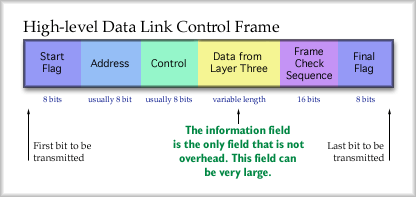
The preceding discussion centered around general techniques for operating a single link between a transmitter and a receiver. Now let's look at a very popular protocol, often used on network routers, such as Cisco routers where it is the default serial line protocol High-level Data Link Control Take a look at this HDLC frame. The first bit to be send on the medium would be on the left so we'll call that the start of the frame. The frame is divided into six fields.
The flag field identifies the beginning of the frame. For HDLC it is always 01111110. An identical flag field marks the end of the frame. Following that is an address field which can be used if more than two stations are using the same medium. The control field is where we put those sequence numbers for go-back-n. ACK and REJ messages also go in the control field. The data field is where layer three information is encapsulated. This is sometimes called the "payload." The frame check sequence is a CRC error check which contains that binary division remainder mentioned earlier in this lesson. Flag Field However, because the end of the frame is not fixed, the receiver will be searching for the 01111110 pattern, which might by coincidence occur naturally somewhere earlier in the frame. That would be bad because the receiver would assume it had reached the end of the frame, back up to locate the frame check sequence bits and perform an error check that would surely indicate an erred frame. To avoid this all fields except the two flag fields are "bit stuffed." Bit stuffing is also called zero-bit insertion. This is easy to do and it prevents any false flags from appearing to chop of the end of the frame. Zero-bit insertion is just that, for all fields between the flag fields, the transmitter inserts an additional zero after every string of five 1s in a row. The receiver watches for strings of five 1s in a row and removes one zero that occurs after those five ones. If six ones and a zero are encountered that indicates the final flag. Example: Use zero-bit insertion on the following bit stream, 0101111111111010. 0 1 0 1 1 1 1 1 1 1 1 1 1 0 1 0 original 0 1 0 1 1 1 1 1 0 1 1 1 1 1 0 0 1 0 final bit stream Boundaries between the fields are not a concern. Bits are counted consecutively. Address Field Using an 8-bit address field there are only 7 bits left for addresses. That would permit ... L = 2n ... 127 unique stations. If the first bit is is a zero, you'd have a 16-bit field. It is left to the student as an exercise to determine the number of stations addresses would be possible. More commonly however, HDLC only links from one station to another. So, there is usually no need for fancy addressing schemes.
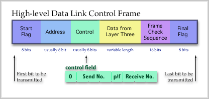
Control field
The control field is 8 bits, usually. The transmitter and receiver agree on the size when the establish a connection. The first bit defines what kind of frame this is. Usually a 0 is located in the first bit and it means that this is an information frame carrying layer three data. A 1 indicates that the frame is just used for acknowledgments and that no information is included. The information field is actually omitted. The remaining seven bits are divided up between the send sequence number, a poll/final bit and the acknowledgment sequence number. That means that the send number is a 3-bit binary number. This permits a window size of 7 frames (23 - 1 = 7 frames). Data Field Frame Check Sequence
Conclusion |
| [INF 680 Syllabus] [How to Start] [Schedule] |
Used with permission of the Author; Copyright (C) Kevin A. Shaffer 1998 - 2022, all rights reserved. |
