|
|
 |
Read Chapter 4 in your tex and study this lesson. Complete hw4. Transmission Media In this lesson we will work on the physical media through which our signals (the symbols, not the bits) are transmitted. Each media has its peculiarities which make it more or less suitable for various purposes. We will study those characteristics and look into the resulting performance. There are two very general categories of transmission media: guided media and unguided media. guided media: Most commonly a wire along which signals travel. the wire (or fiber) carries a signal along a desired pathway between to end points, of course. Typically, guided media that travel over great distance need to have "right of way" to pass over land owned by various people. Railroad companies tend to have excellent right of way, as do power, phone and electrical service utilities. Naturally, over short distances, this is not a problem. An example of guided media is coaxial cable. unguided media: Noted as wireless media in your text, this includes the electromagnetic spectrum, air space and water. Because sound waves do not propagate very far at reasonable volumes we won't be studying sound as a communications medium (although it is one). Water, while quite suitable for long distance communications of whales and dolphins is not used much for telecommunications by humans (well, there is sonar, but it's not really used as a data transmission scheme very often). That leaves us with the electromagnetic spectrum. An example of unguided media is AM radio broadcasting. Guided Transmission Media There are three common types of guided media, twisted pair copper cable, coaxial copper cable and optical cable. Twisted Pair: Copper strands are individually coated with insulating material and two similarly colored strands of wire are twisted together, thus creating a pair.
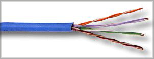
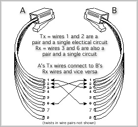
Several pairs may be bundled together and bound by a protective sheath to create a cable. Called an unshielded twisted pair cable, or UTP, this is the most common type of cabling for local area networks, like Ethernet. The graphic above shows that different colored pairs are twisted at different rates. Twisting helps reduce interference between two wires in the same pair. Twisting at different rates helps to reduce interference from one pair to another. The protective sheath is for physical protection, not for shielding. A pair is used as a single complete circuit for transmission (or for reception). A single wire (half of the pair) moves electrons from the source to the destination and the other wire in the pair is used for the return, completing an electrical circuit. Together the pair is used as a transmission channel or a receive channel. Usually, the transmission channel on one end of the wire connects to the receive channel on the other end. Take a look at the following graphic.
Note that A's wire one and two are a pair, representing the transmission line from A to B. The same can be said for B, which has a wire 1 and 2 that are a pair used for transmission from B to A. The cable shown above is called a crossover cable and can be used to directly connect two end stations. This graphic shows that, as is common in Ethernet, only two pairs are actually used. The other pairs will permit an upgrade path to faster Ethernet standards that are coming, though, so it is advisable to install cable that has all four pairs. Very similar to UTP is "shielded twisted pair" or STP. STP includes a foil wrap inside the sheath to protect the internal wire pairs from external electrical interference. UTP costs far less than STP and is much more common. The advantages of UTP include low cost and ease of installation when compared to other guided media. Connectors for UTP also tend to be less expensive than for other guided media. UTP is a very flexible cable and this makes it easier to install than coaxial cable. The disadvantages of UTP are that it has more strict limits on length because it is more susceptible to outside interference and the frequency bandwidth available does not permit data capacities as high as those for other guided media. Coaxial Cable: Coaxial cable, often called coax for short, is constructed with just two conductors, creating a single electrical circuit. The central core of the cable is a solid copper wire strand running down the axis of the cable. The second conductor, the return circuit, is actually a braided mesh tube that surrounds the central copper wire. An insulating sheath separates the two conductors and a heavy covering protects the cable from physical elements. Both conductors have the same lengthwise axis, which is where it gets its name, coaxial.
Why invent coaxial cable? When a current passes along a wire it creates an electromagnetic force that rotates around the wire. We use the right hand rule to determine which direction the force rotates. Point your right thumb in the direction of the current and your fingers will show the direction the force rotates. When multiple wires run beside each other these forces attempt to retard current flowing in the opposing direction. In particular, the other wire in a wire pair has current running in the opposite direction and it is adjacent to the wire creating interference. Ack, this really causes problems. Twisting helps reduce this interference to some degree. However twisting cable makes it shorter, i.e. we have to use more copper to create a cable of a certain length. That makes the cable more expensive. With coaxial cable, the forces are also coaxial and therefore much less of a problem. Coaxial cable can span a greater distance without a repeater than UTP and STP cables. Unfortunately, coaxial cable is more expensive than UTP and it is more difficult to work with. Coaxial connectors are expensive and the cable is stiff, requiring more work during installation. In comparison, the added cost, both in the cable and the installation, is not often justified. This explains why UTP is much more popular in local area networks. Coaxial cable is also losing ground to fiber for long-haul connections. The future is not bright for coax. Optical Cable : Both glass and plastic cables are manufactured to support optical transmissions. Only two strands of fiber are needed to complete a communications channel that can both transmit and receive. Fiber cable can be a single pair or a large bundle of pairs. Fiber bundle with plastic core for tensile strength
Fiber pair for local area network backbones
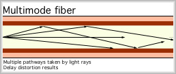
Fiber is very flexible, but if the radius of a bend is to small, the internal fiber will crack and have to be repaired. The most important advantage to fiber is that the signals are not electrical, and therefore it is immune to electromagnetic interference. Fiber cables can travel over much greater distances without the support of repeaters in comparison to copper cables. The most common type of fiber is known as multi-mode fiber. The diameter of the optical path is greater than the wavelength of the light rays that pass along the fiber. The result is multiple pathways within the fiber that the light rays may follow.
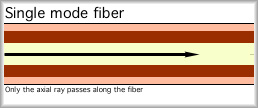
Each of these pathways is a slightly different length and therefore, the light rays travel for different amounts of time. Because the light rays of a single signal arrive at slightly different times, the signal suffers from delay distortion. The effects are similar to delay distortion in copper based guided media, but the technical reasons for this are different. A more expensive version of fiber is called single-mode fiber. The diameter of single-mode fiber is very close to the wavelength of the light rays traveling along the fiber. Because of this, only the axial ray travels down the fiber. This significantly reduces the delay distortion allowing higher data rates and greater distances between repeaters.
A wide variety of advantages have allowed fiber to become popular where its higher costs can be justified. Take a moment to review these on page 82 of your text. * Greater capacity Two of the above advantages need clarification: Repeaters and Capacity. Repeaters: What's the difference between a repeater and an amplifier? You are probably familiar with an amplifier. At least the word may suggest to you that an amplifier boosts the power level of an incoming signal before sending it out again. You are correct, of course. There is one issue with amplifiers, though. Amplifiers increase the noise that has intruded upon the signal right along with the intended signal. the more times you amplify the signal, the more the noise grows in proportion to the signal level. Repeaters have an advantage over amplifiers. The repeater determines the actual digital signals sent (either the bits or the symbols) and then recreates a transmission from the intended signal. The noise is removed. For example if a signal comes in that has a bit of noise attached, but is still distinguishable as a 1101 for example, we can send out a perfect 1101 signal that has no noise in it. Signals do not pass through a repeater, a new signal is created for transmission and sent out based on the actual digital information that was received. A transmission has to be digital to use a repeater. Just as amplifiers, repeaters may be placed in a series along a long-haul cable. However, fewer repeaters are required to cover the same distance. Capacity: We have seen already that the available bandwidth of a channel limits the theoretical maximum transmission capacity (in combination with the signal to noise ratio). Take a look at figure 3.3 in your text, Data and Computer Communications, and notice the bandwidth available for UTP, coax and fiber. Try to confirm the following:
From Shannon's Capacity Theorem (the equation) and assuming a signal to noise ratio equal for each of the media, we can conclude that fiber has a higher capacity than coax and coax has a higher capacity than twisted pair. You can confirm this with a small bit of effort. I'll get you started. Example: What is the maximum capacity theoretically possible on twisted pair assuming a signal to noise ratio of 10:1 and a bandwidth of 1 MHz? C = 2Wlog_2(1+S/N)1/2 Wait a minute. That's not what we figured out about phone lines, which are twisted pair guided media! You should know the answer to this mystery by now: Why can't you get this capacity on your phone line? Standardization of Cable: Cable must be manufactured carefully to meet specification created by standards bodies such as Underwriters Laboratories (UL) and the Electronic Industries Association (EIA). doing so gives us confidence that the cable will support expected bandwidth and interference resistance characteristics. There are a variety of cable standards, but you are most likely to encounter EIA-568-A cables: Category 3: designed to support up to 16 MHz transmissions Perhaps in the very near future, you'll have an opportunity to work with: Category 6 or Category 7: targeting gigabit Ethernet; coming to a LAN backbone near you. Increasing the number of twists per inch allows category 5 to improve upon the characteristics of category 3 wire. Most corporate installations of cabling use "Cat 5" at a minimum and are now considering the cost effectiveness of Cat 6 or Cat 7 for new installations. <Kevin steps up on soapbox> Wireless Media Electromagnetic waves propagate at nearly the speed of light from an antenna (they would go the speed of light if it were a vacuum such as outer space). These waves lose power as they travel, but great distances may still be crossed. Wireless communications include point to point microwave, analog an digital cellular systems (mostly phone), broadcast radio and television, satellite TV broadcast and Telephone services, and private radio such as short-wave and citizen's band (CB) radio. Some of the advantages of wireless communications include: * mobility of transmitters and receivers possible Some of the disadvantages are: * delay on long-haul channels such as satellite telephone calls <Insert shameless plug here> Wavelength and Frequency Wavelength and frequency are related for electromagnetic waves. Knowing the speed of light we can figure out one given the other. c = lf Where c = 3.00 x 10⁸ m/s, the speed of light in a vacuum Example: What is the wave length of Mix 103.3 FM radios transmissions here in Hays, KS? (check your radio dial and you'll see that 103.3 is MHz) c = lf Another Example: What is the wave length of KOA radio, Denver, which broadcasts at 850 kHz in the AM band? c = lf
|
|||||||||||||||||
| [INF 680 Syllabus] [How to Start] [Schedule] |
Used with permission of the Author; Copyright (C) Kevin A. Shaffer 1998 - 2022, all rights reserved. |


