|
|
 |
Read Chapter 11 in your text and this lesson. Then complete hw 11. Chapter 11 in your text introduces LAN concepts and topologies. We'll dig into this content after a final discussion of two WAN protocols. Remember that WAN protocols are generally slow, cover large geographical distances and typically run over common carrier networks, such as a leased PSTN line. So, before we begin with LAN technologies, let's investigate SLIP and PPP. SLIP and PPP are two WAN protocols that are most commonly used by a home computer user when making a dial-up connection to their Internet service provider. SLIP is an older protocol than PPP, with PPP offering some distinct advantages. Serial Line Internet Protocol
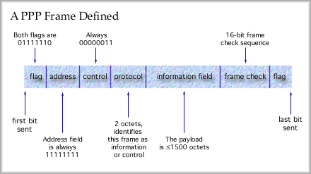
Point to Point Protocol The PPP protocol specification has been adopted by the Internet Engineering Task Force as an Internet standard. The original standard document is available free from the IETF "Request For Comments" documents repository as RFC 1548. In short, the PPP frame looks much like the LAP-B frame. The flag field is fixed as usual (01111110), the address field is fixed (all ones) and the control field is also fixed (00000011). Only the protocol field, the information field and the frame check sequence fields will change. A PPP frame follows. Note how similar it is to a LAP-B frame (a subset of HDLC).
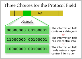
The protocol field can very. The bit combination in the protocol field determines the type of frame sent. The most common frame is one carrying an IP datagram. This is an information field. Link control data for layer two control messages and network control data for layer three control messages can also be sent as shown below.
The PPP specification documents tend to list information in Hexadecimal notation, rather than base 2 or base 10. Please recall that hexadecimal uses 16 unique characters per place in the number. The 16 characters are 0 ~ 9 and then A ~ F. It is quite easy to represent binary values in hexadecimal. Each group of four bits represents one hex character. The control fields shown in the picture above could be represented by: Hex Frame contents Hey, that's much simpler than a bunch of ones and zeros, isn't it. Practice a little. See if you can determine the binary or hex values to complete the following table:
To solve this you would mark off the groups of four bits and then determine the hex value for the group of four bits. Note the four bits can define 16 unique combinations and that there are exactly 16 unique characters in the hexadecimal numbering system. Here are the answers you should have come up with. 6E4F, 11001101 10001001, B015, 10100010 00111101. This has been a hexadecimal reminder public service announcement. If you are having trouble, you might want to refer back to the very first lesson, the Review Lesson, and look into the section on binary. That section discusses converting back and forth from one base to another. It applies to base 16 just as it applies to base 10 and base 2. Because PPP uses a large frame, with an information field up to 1500 bytes, the overhead is much smaller than with SLIP. This is one reason that PPP has become so popular. Another reason that PPP is popular is that PPP supports password authentication when establishing a connection. Both a plain text password challenge (PAP -- Password Authentication Protocol) or an encrypted password challenge (CHAP -- Challenge-Handshake Authentication Protocol) can be exchanged between the two ends of a PPP link in order to establish authenticity.
Difference between LANs and WANs
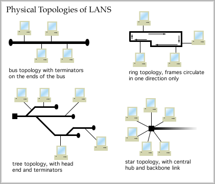
Local Area Networks, LANs In 1982, 10 Mbps Ethernet came on the scene and it was AWESOME. It was also very expensive. By 1988 10 Mbps Ethernet had acceptable performance for large LANs and was still cool for small installations. By 1990, though, large installations were beginning to see congestion and alternatives to 10 Mbps were becoming popular. One of these alternatives was to install a switched architecture, rather than a hubbed architecture. We'll cover this a bit later. In 1996, 10 Mbps switched LANs were providing acceptable service for smaller installations (let's define that as a 100 seat LAN). The awesome technology at this point was 100 Mbps shared Ethernet. By 1998, switched 10 Mbps Ethernet was common in small LANs and switched 100 was common in large LANs. Large LANs are beginning to see limitations of 100 Mbps. You just can't seem to get smooth video conferencing on a busy 100 Mbps LAN when everyone else is trying to do the same thing. Now Gigabit Ethernet cards are available for sale. You can't seem to find 10 Mbps cards very easily. Nor can you find 10 Mbps switches. If you buy an Ethernet card, you will likely get a 10/100 auto-sensing card. I have seen 10/100/1000 auto-sensing cards for sale. In 2000, you'll even have a hard time finding a 10 Mbps switch. They just don't make pure 10 Mbps hardware anymore. Everything is moving to dual mode auto-sensing technology. Even through Gigabit Ethernet is awesome now, it won't be all that awesome in a few years. What in the world would anyone need Gigabit Ethernet for? Well, we could fill that pipe right now if we had it. I'd run my lectures via video directly to each students dorm room at full screen 30 frames per second. That would deliver pretty good quality and you'd be able to actually read the writing on the whiteboard. Example: What is the data rate needed to support 30 screens per second full screen video without data compression and without any encapsulation. What we know: 30 screens per second 30 x 640 x 480 x 8 x 3 = 221,183,000 bits per second. 100 Mbps Ethernet won't handle this. Sure you can compress it, but then of course you have to tack on all those headers in the OSI model. You also have to remember that the video server will have to deliver, for this class, 24 simultaneous packet streams. Oh, if you forget to buy the full duplex 100 Mbps cards, you'll only be getting half the rate, if you are fortunate enough to be using switched 100 Mbps Ethernet. <soapbox> Now, throw in the fact that you'd really prefer to have 1024 x 768 pixel screens and 60 frames per second because you want better clarity and you'd like to have sound with that. That would translate into more than 1.1 Gigabits per second. You'd better compress this to about 1/25th of its original size if you want just 20 people to use this video server with a switched Gigabit Ethernet link. This is a never ending process. As soon as someone comes up with a 'high' capacity service we find a way to fill it up. This suggests there is pent up demand for capacity out there waiting for support. It won't take long to fill up a 1000 Mbps link. If everyone had those right now, we would certainly see TV moving to the Internet. Repeat after me, "I want 100,000,000 channels!" I dare you to channel surf through that. </soapbox> OK, so what is Ethernet anyway? We will investigate how Ethernet works in lesson 13. For now, let's note that Ethernet is a shared medium, meaning that only one person accesses the medium at a time. If someone is using the network, then everyone else has to wait. Ethernet evolved from a protocol called Aloha. This was a packet radio network used to communicate with satellites. In brief, if you had an earth station and had some data to send, you sent it as soon as you were ready. Then you waited to see if you received an ACK. If you didn't get an ACK, you would time out and send again. You keep trying until you are successful. The problem with the Aloha access method is that as more and more users start to access the network there is an ever increasing chance that two people will transmit at the same time. The signals overlap and neither is understandable by the receiver. This is called a collision. A collision represents wasted capacity. Neither transmission is successful and both will have to be sent again. As the number of collisions over time increases, the likelihood of further collisions also increases. This is because of the increase in retransmissions. Through some nasty mathematics is can be shown that the maximum utilization of an Aloha network is only 18%. If the number of collisions increases to a certain point, the network throughput begins to fall. Further increases in transmissions and retransmissions, and re-retransmissions means that throughput will collapse. The network has been saturated with collisions. The lesson to be learned here is that it is important to limit the number of users on a shared network medium. Traffic analysis can help determine the maximum number of users to ensure a reasonable quality of service. Physical Network Topology There are many common physical arrangements for wire guided mediums.
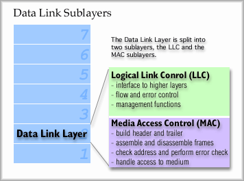
The physical bus topology was very common for early styles of Ethernet. The ring is still very common, being used for Token Ring LANs and FDDI. The tree topology is exemplified by cable TV networks (which support "cable modem" service) and the star topology is the physical arrangement of current Ethernet LANs. The OSI Model and LAN Access The job of layer 2, the data link layer, can be subdivided into two sub layers. Logical Link Control, or LLC: The top half of the data link layer. This sublayer provides flow and error control functions and manages the hand off to and from layer 3. Media Access Control, or MAC: This sublayer resides in the lower half of layer 2. It has the responsibility of knowing the rules of access to the medium and following those rules. It has to assemble the frame by creating and attaching the header and trailer of each frame. It also has to disassemble incoming frames, checking the address information ["Is this frame for me?"] and performing the error check.
LAN standards often specify both layer one and layer two characteristics. For example, Ethernet is explained in excruciatingly fine detail in the IEEE 802.3 standard. Token Ring access rules are explained in the Token Ring standards document, published by the IEEE as standard 802.5. FDDI is another layer 2 LAN protocol with yet another set of access rules. OK, so what does this mean for me and the computer I am about to buy? Well, if you are purchasing a computer and the brochure says that the computer comes with an Ethernet card in it, you now know that your computer will have a network interface card (NIC) that will permit you to connect to an Ethernet LAN. The NIC has a physical connection port on it where you can connect an Ethernet LAN cable. The card is responsible for following the Ethernet access rules. If you wanted to connect your computer to a Token Ring network, you would probably buy a Token Ring NIC and install the card (perhpas in place of your Ethernet NIC). You would install some driver software so that the system would recognize the Token Ring card and use it for network access. The Token Ring card would follow Token Ring network access rules and give you access to the Token Ring LAN. You see now that a completely different set of rules are followed for different LAN access methods. So, what are the common access methods? Media Access Methods Contention: Users compete to gain access to the medium. This may be a first come first served approach like Aloha. Ethernet users also compete for access to the network. Luck may play a factor in how soon you can send your frame. Round Robin: Users take turns in order. Token Ring and FDDI users take turns. Efficiency seems to be better with this scheme than with a contention scheme. Reservation: Users may mark passing frames to claim the next available chance to use the medium. Token Ring support this feature. LAN equipment Repeater: Operates at layer one. Has just enough intelligence to figure out what the layer one incoming signals are and then send out a clean stream of signals built from scratch. Noise is eliminated from the signals in this manner. A repeater has one incoming and one outgoing line. It extends the distance that a signal may be sent. Hub : A hub is a multiport repeater. Any incoming signal is repeated on all other outgoing lines. A hub functions at layer one. Bridge : A bridge has more intelligence than a hub or repeater. This device separates two segments of a single LAN. A bridge operates at layer two by looking at the destination address in the frame header. Consulting a table, the bridge will determine if the frame needs to pass on to the other segment. Think of a bridge as a police officer. Only certain frames may pass, those with the correct credentials. Switch: A switch is a multiport bridge. It performs its functions at layer two. It looks at MAC layer addresses just like a bridge, consults a table and determines if a frame needs to be sent on one of the attached lines. Multiple connections can occur through a switch simultaneously as long as they don't compete for the same line. A switch, just like a bride, does not divide a LAN into two LANs. It merely reduces unnecessary traffic on LAN segments. Router : A router is more intelligent than bridges and switches. It functions at layer three. Incoming frames are checked for errors and then the payload is delivered to layer three. A layer three datagram has an address that permits it to be sent across internetworks (interconnected networks). This requires a single global addressing scheme. The router finds the layer three address and consults a table that it keeps. There the router will learn which attached line to send the datagram on. A router provides stations on the LAN access to other networks.
|
| [INF 680 Syllabus] [How to Start] [Schedule] |
Used with permission of the Author; Copyright (C) Kevin A. Shaffer 1998 - 2022, all rights reserved. |


